Living close to a densely populated area means that it's hard to do consistent testing without spending a lot of fuel, which is also expensive.
Nevertheless, I took the pen&paper approach and started working my way from the basics.
I studied all the Bosch sensors from this page, used a bit of common sense and figured out that my sensor is a Bosch 0281002691, or similar, with a 180 MPa (26000 psi) nominal rating. This might be wrong but It's a good place to start.
I've already used Torque and my multimeter to get some data and it seems to fit with the sensor I've chosen. It might be wrong, but so far it clicks into place.
Using the data I've gathered I've created a simple JS page that shows some logs and tries to simulate what my module (and sensor) does: https://jsbin.com/goyavabuju/edit?html,output
(Note that this is the HTML/JS result after I did the interpolation.)
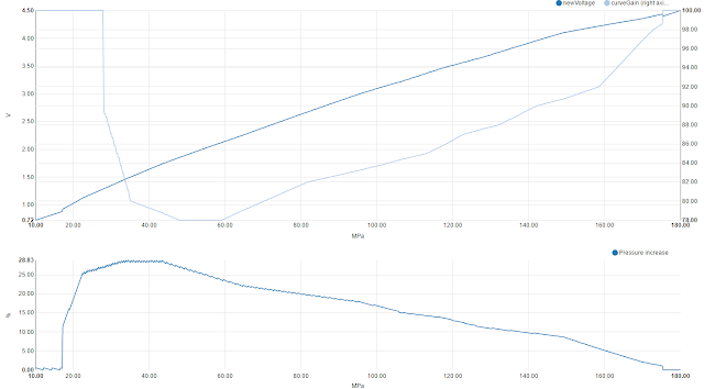
So the basic function is: the ECU commands the pump, this delivers a pressure, my module receives the sensor data (voltage), offsets it, outputs a new voltage to the ECU, the ECU processes it. I missed a step the last time: the ECU will receive the adjusted pressure, output a new pressure, the pump delivers, a new pressure is measured. This can cause oscillations within the engine, as the tuning module attempts to adjust for the new value.
My goal with the JS/HTML page was to see what the output (after one step) would be, and see that it does not exceed the nominal values. In case of the sensor it should not go below 1V for a running engine or above 4.5V. Anything outside those boundaries would trigger a 'bad sensor' alert inside the ECU.
I simulated the tuning module response and the result I got back was that at the top-end range the sensor was out-of-spec. This is not ok and it also was a reason why sometimes (cold, hill, heavy car, sports mode, heavy acceleration) the engine light would turn on. You have to remember that the rail pressure sensor measures load not power.
Second step was to smooth out the response. A real car would not go into hard steps and would not artificially delay the response (RaceChip?). So I implemented a very simple linear interpolation. If you have a range of 500-600 with a gain of 80% and a range of 600-700 with a gain of 90% the software would do this:
In the end it turned out that the ground was 'ungrounded', i.e. the signal generator, oscilloscope and arduino were floating. Normally this is a good thing, except when unexpected. I spent a few hours chasing the problem down (RC output combinations, input filters, voltage, input and output impedances, etc.).
I revived a testing page from my ionic2 application and added terminal logging and a basic oscilloscope. I left the application linger for a while as I a) expected ionic2 to mature a bit b) expected me to learn a bit more c) expected Cordova to add browser BT-UART support. None of these happened so I worked with what I had.
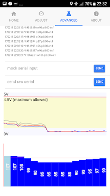

The screenshot shows the raw UART log, a rolling graph for the values mapped onto a 0-5V scale and an experimental feature that I gave up on implementing: draggable curve points.
There is a peak where I floored the car to kickdown.
During a casual code self review (I really wish someone would audit my code) I found a few bugs and warnings in the Arduino implementation. One of those had to do with firmware response at extreme values (at or beyond min and max).
The code for the changes above is not in GitHub yet (as of 12 Feb 2017), but except the interpolation feature and small bugfixes the circuit functions exactly the same.
My initial tuning values were sometimes exceeding the allowed 4.5V absolute maximum, so I've turned them down a little. But I also over-tuned the low-range, which caused the car to shake wildly at idle, when the engine was cold. So I had to change points 0 and 1 from ~78 to ~88.
Excerpt of the log, showing settings, live tuning and other stuff: http://pastebin.com/xk1xdQ9g
I cannot draw any final conclusion on consumption as I need to use at least 15 liters of fuel. But as a baseline, without the circuit, I'm getting around 12L/100km city average, the OBC is also spot on. It's cold, winter, and I'm doing mostly short city trips.
Will report in a week or two with real data, taken from refueling measurements.
Nevertheless, I took the pen&paper approach and started working my way from the basics.
I studied all the Bosch sensors from this page, used a bit of common sense and figured out that my sensor is a Bosch 0281002691, or similar, with a 180 MPa (26000 psi) nominal rating. This might be wrong but It's a good place to start.
I've already used Torque and my multimeter to get some data and it seems to fit with the sensor I've chosen. It might be wrong, but so far it clicks into place.
Using the data I've gathered I've created a simple JS page that shows some logs and tries to simulate what my module (and sensor) does: https://jsbin.com/goyavabuju/edit?html,output
(Note that this is the HTML/JS result after I did the interpolation.)

So the basic function is: the ECU commands the pump, this delivers a pressure, my module receives the sensor data (voltage), offsets it, outputs a new voltage to the ECU, the ECU processes it. I missed a step the last time: the ECU will receive the adjusted pressure, output a new pressure, the pump delivers, a new pressure is measured. This can cause oscillations within the engine, as the tuning module attempts to adjust for the new value.
My goal with the JS/HTML page was to see what the output (after one step) would be, and see that it does not exceed the nominal values. In case of the sensor it should not go below 1V for a running engine or above 4.5V. Anything outside those boundaries would trigger a 'bad sensor' alert inside the ECU.
I simulated the tuning module response and the result I got back was that at the top-end range the sensor was out-of-spec. This is not ok and it also was a reason why sometimes (cold, hill, heavy car, sports mode, heavy acceleration) the engine light would turn on. You have to remember that the rail pressure sensor measures load not power.
Second step was to smooth out the response. A real car would not go into hard steps and would not artificially delay the response (RaceChip?). So I implemented a very simple linear interpolation. If you have a range of 500-600 with a gain of 80% and a range of 600-700 with a gain of 90% the software would do this:
- measure the input value (let's say 580)
- compute the next gain point (600-700 @ 90%)
- compute ratio: 580 is 80% away from 80% and 20% away from 90% => 80%*(100%-80%)+90%*(100%-20%) => 88%
- I might have gotten it wrong above, but the software is right
- multiply the read value (580) with the calculated gain value (0.88), output the new value (510.4)
The result is a much smoother response, verified through the simulation.
The problem is that steps below (especially below minimum) don't matter much, but that can be adjusted for, especially when you can see the response.
Next, hardware, I've taken the entire thing back to the breadboard.
This is where it got interesting - the values from my board were entirely off compared to the the ones received from the signal generator. It felt 'unbalanced.


I know it's ok to fail while experimenting, but it's frustrating when you know it should work and you did nothing wrong. It turned out the circuit was very well behaving and following the simulation results very closely.
Above left is circuit response enabled, right is with it disabled. Yellow is input, blue is output.
Above left is circuit response enabled, right is with it disabled. Yellow is input, blue is output.
Software client/app:
I revived a testing page from my ionic2 application and added terminal logging and a basic oscilloscope. I left the application linger for a while as I a) expected ionic2 to mature a bit b) expected me to learn a bit more c) expected Cordova to add browser BT-UART support. None of these happened so I worked with what I had.


The screenshot shows the raw UART log, a rolling graph for the values mapped onto a 0-5V scale and an experimental feature that I gave up on implementing: draggable curve points.
There is a peak where I floored the car to kickdown.
During a casual code self review (I really wish someone would audit my code) I found a few bugs and warnings in the Arduino implementation. One of those had to do with firmware response at extreme values (at or beyond min and max).
The code for the changes above is not in GitHub yet (as of 12 Feb 2017), but except the interpolation feature and small bugfixes the circuit functions exactly the same.
Testing
My initial tuning values were sometimes exceeding the allowed 4.5V absolute maximum, so I've turned them down a little. But I also over-tuned the low-range, which caused the car to shake wildly at idle, when the engine was cold. So I had to change points 0 and 1 from ~78 to ~88.
Excerpt of the log, showing settings, live tuning and other stuff: http://pastebin.com/xk1xdQ9g
I cannot draw any final conclusion on consumption as I need to use at least 15 liters of fuel. But as a baseline, without the circuit, I'm getting around 12L/100km city average, the OBC is also spot on. It's cold, winter, and I'm doing mostly short city trips.
Will report in a week or two with real data, taken from refueling measurements.
Hello.
ReplyDeleteI would like to try and play with it a little bit.
which is the last complete scheme with arduino nano?
have there been any further developments?
best regards
Giulio
The schematic is the same as on the github link. I could not measure any improvements at low rpm with any settingssettings, so I abandoned the project for now until I can find a way to reliably measure consumption.
Delete