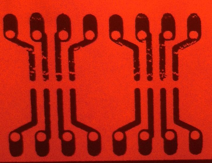
 |
| Completed prototype board |
The bane of a lot of software guys is moving up from the ubiquitous breadboard to a self-made PCB. The other common fear is switching from through-hole parts to surface-mount technology.
Having resorted in the last years to PCB fab houses or friends to etch the boards from me I decided to man up and do some SMD breakout boards for myself. There are quite a few advantages to this:
- a lot of new chips are available only in SMT or are cheaper to buy than PDIP
- no drilling
- more compact and able to work at higher frequencies
- higher pin-count chips delivering more input/outputs and better performance in general
The reason for doing this is that I have a lot of SMD devices that I need to use: DC power supplies, OPAMPs, voltage regulators, 555, resistors and capacitors, etc. and otherwise they would sit unused. Plus, a steady supply of broken motherboards is able to give you logic-level MOSFETs, voltage references, inductors, EEPROMs, ...
Rather than start from scratch, there's a nice topic providing some ready-made SMD to DIP adapters at http://www.mikrocontroller.net/topic/225181.
The toner transfer method is pretty quick once experience sets in:
- board cleaning - 1-5 min
- printing the transfer - 1-5 min
- laminating - 2-7 min
- softening - 30 min of waiting
- cleaning the paper - 1-3 min
- etching - 1-5 min
- cleaning the board - 1-5 min
Supplies:
- single-sided or double-sided blank PCBs (around 1 EUR)
- etching agent: ferric chloride or muriatic/hydrochloric acid or hydrogen peroxide or sodium persulfate (2-8 EUR for a lifetime supply)
- rubber gloves (2 EUR for 50 pairs)
- dish sponge
- laser printer (I paid 20 EUR for a refurbished one)
- laminator (I paid ~10 EUR for a new one) or clothes iron
- spam magazine or catalog (with cheap, thin and shiny pages)
- alcohol or acetone (nail polish remover)
- clear tape and/or masking tape
Most of the stuff you should already have inside the house.
Etching agent:
Ferric chloride can be found at most electronic/hobby shops but you can go the household way and purchase any other agent. Hydrochloric acid is found in strong toilet cleaners, look for the ingredients on the back label. Hydrogen peroxide is used for bleaching hair.
The stronger the etching agent the less work you have to do. With a 10-year old supply of ferric chloride and the technique described below I am able to etch a board in 3-5 minutes, but it can probably be done faster than that.
Blank PCBs:
You can buy a large sheet but I suggest that you buy several smaller sheets, not larger than 20x20 cm. Since the single-sided and double-sided boards have almost the same price you could buy directly a double-sided board and be ready when you want to make the switch to double-sided etching.
Gloves, sponge, catalog:
Rubber gloves are essential, ferric chloride will stain everything around and all agents are corrosive.
Reserve a separate non-metal bowl for etching duties, I used a TV-dinner single-use food container. All ceramic and almost all plastic containers should work. It should have a large area rather than be deep.
The sponge is the normal supermarket type with a rough side and a soft foam side, normally used for washing dishes.
The catalog is not mandatory but allows for a better quality. Just take any cheap spam magazine with glossy pages and carefully detach the pages from the spine.
Steps:
Layout:
Design the board in Eagle or just download a ready-made one from the first link in this post. In my example I'm just placing random SMD components and use the result as a prototyping board or just cut out the pieces I need.

 |
| THT tryout |
Make sure you draw a thick line surrounding your design, it helps in avoiding toner ripping off the board. You can see on the right that one corner came unglued but the overall design stayed intact.
By the way, this board was made without using the glossy magazine paper, only with normal printer paper. That's why there's a lot of paper pulp showing and why toner failed to adhere in some places.
Print the board on normal paper for testing. Turn off your printer's optimizations and turn the DPI value to maximum. Make sure you select the layers that you need (top, pads) and use the settings below if in doubt.

Check if the blank PCB matches with the (mirrored) printed design. Check scaling against a known reference.
Printing:
Rip out a page from the glossy magazine and glue it to a printer sheet using the masking tape (or clear tape). You might get away without doing this step but my printer gets jammed if I'm using only the thin paper.
The tape should go around the glossy page (which is smaller than A4/Letter) and the page should be laid very flat so it does not get stuck in the printer.
I don't really recommend clear tape as it might melt or leave residue on the printer drum, this is why masking tape is better.
Print the sheet and avoid touching the printed area with your hand to avoid grease deposits.
Preparing the PCB:
My PCBs were really old and oxidized so I used a bit of sanding paper (400 grit) to get rid of the surface oxides. You could also use a wire sponge or wire brush until the surface has a clear yellow/light orange shine. Tiny scratches won't really matter, see the "THT tryout" picture above.
Wash the PCB with soap or detergent, dry it and then clean it with alcohol or acetone. From this moment on only hold it by its sides (like a CD), any grease deposits will prevent the toner to adhere to its surface.
Laminating:
Tape the PCB to the printed paper using clear tape (or masking tape) and you might want to flip the sides over so they don't move.
 You can see in the picture that I cut the paper and then fold it over the sides but it's actually better if you don't cut excess paper. It would allow you to pull the contraption out of the laminator if it gets stuck and it also laminates better.
Having too much excess paper will cause the thing to become too thick and heat will not transfer properly and it also might get stuck.
Heat up the laminator and run the contraption through it for a few times: five times on the top, five times on the bottom, alternating. The more you do it the better, but check below for a hint.
Some people have suggested that preheating the board improves the toner transfer. I find that running the thing through before it's completely warmed up is the same thing.
If you don't want to buy a laminator you can use a normal clothes iron and 'simulate' the action. 10-20 passes with 2-5 kg of force will usually get the job done.
Checking the result:
Leave the board in a bowl of water (or plugged sink) for circa half an hour. This is needed to soften the paper making it easier to remove without ripping the toner off. Remove the normal paper by ungluing the tape tearing it apart.
Using the tip of your fingers, rub lightly on the glossy paper until it comes off. If it comes off with the toner and traces then you would have to start again: clean the board with rough side of sponge, degrease it, print and prepare another paper, laminate thing.
 If all goes well you should be left with the result on the right.
Wash the board thoroughly with water to remove any remaining paper pulp. Do not use anything other than the tip of your fingers to avoid damaging traces.
Inspect the board again and check for missing traces or other defects. Using a fine-tip permanent marker redo the missing bits. If that's not possible, start over from board prep.
 For example, the SO-8 layouts on the right half, the right-side pads are looking a bit interrupted so I used an "Edding Worx-3 Liner" 0.7mm permanent marker.
If the tracks look like they are "bleeding" then you have used too much heat or the laminating pressure was too high.
Make a last inspection since that's the only step when corrections are possible.
Etching
Put your rubber gloves on, dip the sponge into etchant (or pour a small amount carefully on top of the sponge) and CAREFULLY rub the board in all directions and places. Do not place any pressure on the sponge, its wet weight is enough. Keep the board in one hand and the sponge in the other, it's easier this way.
Make sure to keep an even pressure and number of passes on the entire board surface, not just the on the center. Do not rub too hard or too dry or you might rub the toner off.
After 10-20 light scrubbing motions (~30 seconds) wash the board under running water and inspect it. You might see some areas that are not shiny anymore, this is where the copper has been etched away.
Shake dry the board, dip the sponge, repeat scrubbing, but avoid rubbing on the already-etched areas.
Do this until all (relevant) copper has disappeared from the board.
If you are using a single side of a double sided board just do the unprinted side first and then the rest.
Cleaning and final inspection
Use the rough side of the sponge and a detergent to scrub away the toner. You might try acetone or alcohol to dissolve the toner but it did not work for me.
Put the board against a light source and check for missing bits or unwanted bridges.
On the board below I did not manage to correct the problem with the marker, so I'm left with a hairline crack on some pins:
Since they are about 0.1mm in size and right under the chip's pads they might get bridged properly. Besides, the reason for having several copies of the same package is to avoid "manufacturing defects".
Conclusion
As you can see from the Eagle layout, the packages include breakout pins compatible with a DIL header or DIP spacing. To use those you would have to cut the interesting parts apart, drill the holes and install the headers.
It took me about 90 minutes (including undoing a mistake) to etch this and about the same time do do the write-up. I'm disappointed that I did not take enough pictures but I was with the gloves most of the time.
Still, I'm happy with the result and I can finally put those sample chips to good use. I've also used this method for TQFP chips and it might just work with those leadless packages.
Sorry, can't help you with BGA.

Comments
Post a Comment
Due to spammers, comments sometimes will go into a moderation queue. Apologies to real users.